Modulo 6 counter jk flip flops Ripple counter Counter circuit diagram counter circuit diagram using flip flop
Ripple Counter - Circuit Diagram, Timing Diagram, and Applications
Counter circuit using flip flop For the flip-flops in the counter in circuit below, Solved design a synchronous counter circuit using d flip
Jk flip-flop counter synchronous circuit electronic circuit, png
Counter ripple timing flip jk flop using diagram circuit bit truth table binary diagramsFlip flop jk counter synchronous circuit electronic diagram save bit Up down counter circuit using jk flip flop3 bit up down counter state diagram.
Solved design an arbitrary synchronous counter circuit using[diagram] logic diagram of d flip flop Cd4027 jk flip flop pinout, examples, working, datasheet, applicationsDesign a counter using t flip-flop || logic circuit || board exam.

Flip flop circuit.
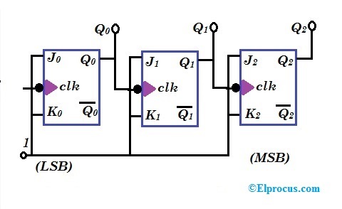
1: a 4 bit ripple counter circuit. the output of one flip-flop clocksCounter ripple flip flop clocks count hence asynchronous counters rantle Flip flop jk table electronics truth rs typesDesign a synchronous counter using d flip flop.
Design a counter circuit using jk flip-flops based on(solved) : counter designed jk flip plop redesign circuit d flip flop t Solved 4. design the counter circuit with j-k flip-flopsSolved 1. use jk flip-flops to design a counter with.

Solved for the flip-flops in the counter in circuit below,
Flip flopFlop arduino electronique components schaltung electrique outlook uupload schema raspberry elektroniken électrique 17. the bcd (mod10) synchronous up counter circuit constructed with dSolved: refer to the flip-flop circuit below. assume the counter starts.
Jk flip flop counter circuit usingCounter synchronous bcd flip mod10 flops constructed murat fig19 Flop flip jk counter bit using ic pinout segment sevenDesign a mod-5 synchronous counter using d flip flop.

Solved: design a synchronous counter using jk flip flop with the help
Electronic – problem with the 74160 decade counter – valuable tech notesAsynchronous ripple counter verilog code Up counter circuit using jk flip flopCircuit analysis design a bit binary counter using d flip flop.
Solved do as prompted: 1) make the diagram of a down counter[diagram] asynchronous counter t flip flop timing diagram Ameise wollen schädlich 2 bit counter using d flip flop kabel exotischState diagram for 4 bit counter.
![[DIAGRAM] Asynchronous Counter T Flip Flop Timing Diagram - MYDIAGRAM](https://i.ytimg.com/vi/nSMpwmgMQNc/maxresdefault.jpg)